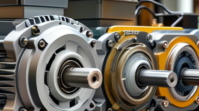

An Electrical Fan Motor quietly converts electrical energy into airflow. Behind a ceiling fan, ventilation unit, or cooling tower, its rotor turns inside a magnetic field. That motion drives blades, moves air, and removes heat from occupied spaces or equipment. The process sounds simple. It is not.
The International Energy Agency reports that space-cooling electricity demand could more than triple by 2050 without stronger efficiency measures. The U.S. Department of Energy also identifies motor-driven systems as responsible for roughly 70% of industrial electricity consumption. These figures explain why motor design matters beyond comfort. A small efficiency loss, repeated across thousands of operating hours, becomes a significant energy cost.
William Cory, author of Fans and Ventilation: A Practical Guide, describes a fan as “a machine which produces a pressure difference and causes air to flow.” His definition remains useful because it connects motor speed, blade shape, pressure, and airflow. Still, it leaves out practical weaknesses. Heat, dust, voltage variation, bearing friction, and poor installation can shorten service life. A motor may spin, yet perform badly.
This guide examines how an Electrical Fan Motor creates torque, controls speed, and transfers power to the impeller or blades. It also considers AC and DC designs, capacitor operation, brushless control, efficiency ratings, noise, and routine inspection. Expect clear explanations, not idealized diagrams alone. Real motors vibrate. Bearings wear. Measurements can disagree. Understanding those imperfections helps technicians choose, install, and maintain fan motors with greater confidence.
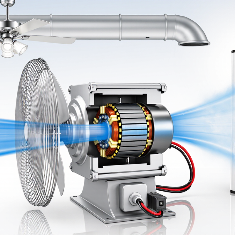
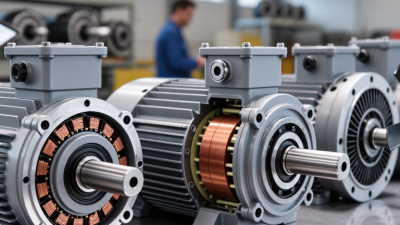
An electrical fan motor is the working core of a fan. It converts electrical energy into controlled rotation. The stator creates a magnetic field, while the rotor turns inside it. This rotation drives the fan blades and moves air through a room, machine, duct, or cooling system.
Its main functions are speed control, airflow generation, heat removal, and stable operation. Some motors use alternating current, while compact systems may use brushless direct current. A controller can adjust speed according to temperature or airflow demand.
The International Energy Agency has reported that electric motor-driven systems consume about 46% of global electricity. This figure covers many applications, not fans alone. Still, it shows why motor efficiency deserves attention.
A small efficiency loss becomes meaningful during long operating hours. The explanation sounds simple, but real performance also depends on blade design, bearing condition, voltage quality, and installation space.
Tips: Check the motor’s rated voltage, power, speed range, and airflow requirements. Keep vents clear and inspect dust around the housing. Excessive noise often signals bearing wear or imbalance. Do not judge efficiency from wattage alone. Measure airflow as well. A lower-watt motor may move less air, creating a misleading saving. I may be oversimplifying one point: reported efficiency can change under different loads. The U.S. Department of Energy also recommends evaluating the complete motor system, rather than the motor separately.
What Is an Electrical Fan Motor and How Does It Work?
An electrical fan motor changes electrical energy into rotational movement. Inside, the stator remains fixed while the rotor turns around the central shaft. Copper windings in the stator create a changing magnetic field when current flows. This field pulls the rotor around. The attached blades then push air through the room.
Several small parts control this movement. The shaft transfers torque from the rotor to the blades. Bearings support the shaft and reduce friction, although dust can shorten their service life. A capacitor helps many single-phase motors start and maintain smoother rotation. The outer housing protects the windings and helps release heat. Insulation separates the copper wires from the metal core. Some motors also include a thermal protector that cuts power during overheating.
Details matter. A humming motor may have a weak capacitor, blocked blades, or damaged windings. A technician should disconnect power before inspection. Never judge the motor by sound alone. In practical maintenance, a loose bearing can resemble an electrical fault. This explanation also has limits, because motor designs vary between fan types. Testing voltage, resistance, and capacitor condition gives more reliable evidence than guessing. A slightly warm housing can be normal, but a burning smell needs immediate attention.
| Component or Dimension | What It Is | How It Works | Typical Materials or Values | Practical Importance |
|---|---|---|---|---|
| Stator | The stationary part surrounding or supporting the rotating assembly. | Its windings create a changing magnetic field when energized. | Laminated electrical steel core with insulated copper or aluminum windings. | Determines much of the motor’s magnetic performance, efficiency, and heat generation. |
| Rotor | The rotating part mounted on the motor shaft. | Magnetic interaction with the stator produces torque, causing the rotor and fan blades to turn. | Squirrel-cage rotor in induction motors, or permanent magnets in many brushless DC motors. | Affects starting behavior, speed, vibration, and operating efficiency. |
| Motor Windings | Coils of insulated conductive wire placed in slots in the stator. | Current flowing through the coils generates the magnetic field required for rotation. | Usually enamel-insulated copper wire; winding resistance varies with motor size and design. | Wire size and coil arrangement influence torque, current draw, and temperature rise. |
| Motor Shaft | The mechanical member that transfers rotation from the motor to the fan assembly. | It carries torque from the rotor and spins the hub or blade mount. | Commonly made from hardened or stainless steel; alignment is critical. | Poor alignment or bending can cause noise, vibration, and premature bearing wear. |
| Bearings or Bushings | Supports that allow the shaft to rotate with reduced friction. | They maintain shaft position while carrying radial and, in some designs, axial loads. | Ball bearings use rolling elements; sleeve bushings commonly use sintered or oil-impregnated materials. | Lubrication, load rating, and operating temperature affect service life and noise levels. |
| Capacitor | An electrical component used mainly in single-phase AC fan motors. | It shifts the phase of current in an auxiliary winding to create a rotating magnetic field and starting torque. | Often a permanent split capacitor design; capacitance is selected for the specific motor circuit. | A weak or damaged capacitor can cause humming, slow starting, overheating, or reduced torque. |
| Electronic Controller | A circuit that regulates power in electronically commutated or brushless fan motors. | It switches current through the windings in a timed sequence and can adjust speed using pulse-width modulation. | Typically includes power switches, control logic, sensors, and protective circuitry. | Enables efficient speed control, soft starting, overload protection, and stable operation. |
| Thermal Protection | A device or function that limits damage from excessive temperature. | A thermal switch, fuse, or electronic controller interrupts or reduces current when overheating is detected. | Protection temperature depends on the motor’s insulation system and design. | Helps protect windings from insulation breakdown caused by overload, blocked airflow, or stalled rotation. |
| Motor Housing | The enclosure that supports internal parts and protects them from mechanical damage. | It holds the stator and bearings in alignment and may transfer heat to the surrounding air. | Stamped steel, die-cast aluminum, or engineering-grade plastic, depending on the design. | Housing rigidity, ventilation, and sealing influence vibration, cooling, and durability. |
| Fan Blades and Hub | The aerodynamic assembly attached to the motor shaft. | Rotating blades accelerate air and convert motor torque into airflow. | Commonly molded polymer or stamped metal; blade pitch and diameter vary by application. | Blade geometry affects airflow, static pressure, noise, power demand, and balance. |
| Electrical Input | The voltage and frequency supplied to the motor. | Electrical energy is converted into magnetic force, mechanical torque, and ultimately airflow. | Common supply systems include single-phase AC or low-voltage DC; ratings must match the motor label. | Incorrect voltage or frequency can cause overheating, poor performance, or insulation damage. |
| Speed and Power Range | Operating characteristics that describe how fast the fan rotates and how much electrical power it uses. | Speed is determined by motor type, supply frequency, control method, load, and selected operating setting. | Small household and equipment fans commonly operate from a few watts to several hundred watts, with speed varying widely by design. | These values help determine airflow capacity, energy consumption, noise, and suitable applications. |
What Is an Electrical Fan Motor and How Does It Work?
An electrical fan motor changes electrical energy into rotational motion. When current enters the motor, it creates a magnetic field around stationary wire coils. This field pushes and pulls the rotor, the moving part inside the motor. The rotor begins to turn. Its shaft then transfers that motion to the fan blades.
In many household fans, a capacitor helps create a timing difference between magnetic fields. This difference gives the rotor enough starting force. As the rotor spins, the blades move air across the room. More electrical power does not always mean better airflow. Blade shape, motor condition, and airflow resistance also matter. A dusty motor may run hot and lose efficiency. I have seen quiet fans become noisy after small bearing problems. That detail is easy to overlook.
Tips: Keep air vents clean and unplug the fan before inspection. Listen for grinding, uneven speed, or a burning smell. These signs may indicate worn bearings, damaged insulation, or an overloaded motor. Do not spray liquid into the housing. A qualified technician should test internal wiring and capacitors. My practical view is simple: regular cleaning helps, but it cannot repair hidden electrical damage.
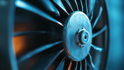
An electrical fan motor converts electrical energy into the rotation that moves air. Inside, copper windings create a changing magnetic field around a stationary core. This field interacts with magnets or an energized rotor. The rotor turns around its shaft. A fan blade hub is fixed to that shaft, so each electrical cycle becomes mechanical motion. In a typical household fan, the motor may rotate hundreds or thousands of times per minute. The blades push air forward by changing its pressure and direction. Airflow depends on blade angle, speed, diameter, and housing clearance. It is not simply “more speed equals more comfort.” Noise and turbulence can rise quickly.
When power reaches the motor, a control circuit regulates voltage or current, depending on the design. Bearings support the shaft and reduce friction. If they dry out or become misaligned, the motor may hum, heat up, or struggle to start. A capacitor can create the phase difference needed for smooth starting in some motors. During inspection, I would listen for uneven rattling and feel for unusual heat after several minutes. This method is useful, but not perfect. Room temperature and dust can mislead the diagnosis. A fan that spins freely by hand may still have an electrical fault. Always disconnect power before opening any cover.
Tips: Keep the grilles clear. Dust on the blades adds imbalance and reduces airflow. Check the cord, plug, and vibration regularly. Do not force a stalled blade. If burning smells, sparks, or repeated overheating appear, stop using the fan and contact a qualified technician.
An electrical fan motor converts electrical energy into the rotating force that moves air. Inside the housing, magnetic fields push the rotor around a fixed stator. The blades then create airflow through the fan grille or duct.
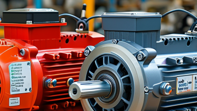
Common motor types behave differently. Induction motors are durable and suit larger ventilation systems. Permanent split capacitor motors are simpler and often used in household fans. Electronically commutated motors use electronic switching and permanent magnets. They usually offer better speed control and lower energy use.
Controls shape both comfort and motor life. A wall switch provides basic on-and-off operation. A speed controller changes voltage or electronic signals, depending on the motor design. Using the wrong controller can cause humming, overheating, or weak starting. Check the motor’s rated control method before installation. The label is not always enough.
Efficiency depends on more than the motor’s advertised rating. A clogged filter makes the motor work harder. Tight bearings can increase noise and current draw. In field checks, I look for dust buildup, unusual vibration, and a hot casing. A small temperature rise may be normal, but a sharp change deserves attention. Airflow measurements also reveal problems that sound alone can hide.
Variable-speed operation can reduce wasted energy during mild demand. However, frequent rapid adjustments may create unnecessary electrical stress in some systems. That detail is easy to overlook. Proper voltage, clean ventilation paths, balanced blades, and scheduled inspection usually matter as much as motor design. Performance records should include current, noise, temperature, and airflow readings. Sometimes the simplest measurement exposes the real fault.
0086-13586199782