

How to Choose the Right Centrifugal Pump Motor?
Choosing a Centrifugal Pump Motor starts with the pump’s real duty, not a guess based on horsepower alone. The motor must deliver the required flow and head while handling the fluid, operating schedule, and site conditions. A clear selection reduces overload risk and helps avoid wasted energy.
Pump reliability author Heinz P. Bloch is known for practical guidance on equipment selection. A useful summary of that approach is: “Choose for the actual operating duty, not the catalog headline.” This is a paraphrase, not a verified direct quotation. It points to the details that matter: fluid density and viscosity, pump speed, available voltage, and expected hours of operation. A motor that looks adequate on paper may struggle when the fluid is heavier or the system demands more head.
Look closely at the pump curve and motor nameplate. Check rated power, voltage, frequency, enclosure, and service conditions. If a variable-frequency drive is planned, confirm motor compatibility and cooling at reduced speed. Small details matter. A hot, dusty pump room is not the same as a clean test bench. Real installations are messier, and assumptions deserve a second look. This guide explains how to compare motor ratings, match the motor to the pump’s operating point, and avoid common sizing mistakes. It cannot replace a site-specific review, but it can help you ask sharper questions before choosing.
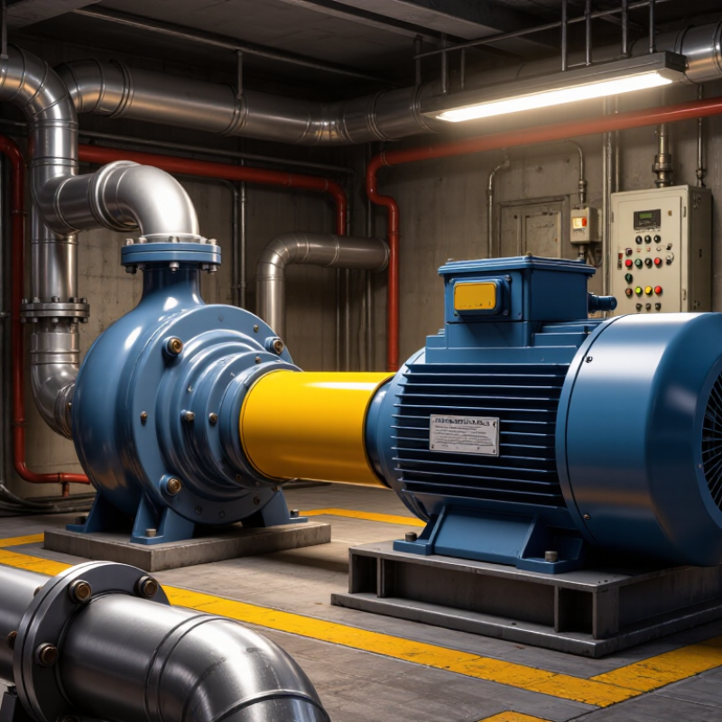
Define the Pump Duty and Operating Conditions
Before selecting a centrifugal pump motor, define the required flow rate and total head at the actual operating point. A pump serving a storage tank may face different demands as the tank level changes. Record both the normal duty and any short periods of peak demand. Check the pump curve against these conditions; a single headline flow figure is not enough. This is where estimates often go wrong.
Describe the liquid and installation, too. Note its temperature, density, viscosity, and whether it contains suspended solids. These factors can change the power the pump needs. Record suction pressure, pipe losses, elevation, ambient temperature, and expected operating hours. Also consider frequent starts, variable-speed control, and whether the pump runs continuously. A motor selected from ideal conditions alone may struggle on a hot day or during a demanding startup. I have seen assumptions look tidy on paper, then need revision once site details emerge. That is worth admitting.
Tips: Confirm the duty point with measured or verified data. Compare required shaft power with motor output across the operating range, and leave an appropriate margin for real conditions. Avoid oversizing by habit: an oversized motor can operate inefficiently, especially when the pump rarely reaches peak demand.
How to Choose the Right Centrifugal Pump Motor? - Define the Pump Duty and Operating Conditions
| Duty or Operating Parameter | Example Value | Why It Matters for Motor Selection |
|---|---|---|
| Pumped liquid | Clean water at approximately 20°C | The liquid’s properties affect pump power demand. Confirm the actual liquid and its temperature before using water-based performance data. |
| Required flow rate | 50 m³/h | Flow is one part of the duty point. Select a pump that can deliver it at the required head, and check that the duty is within the pump’s acceptable operating range. |
| Required total head | 30 m | Head and flow together determine hydraulic power. Include the system’s static lift and friction losses when establishing the required head. |
| Pump efficiency at duty point | 70% (illustrative assumption) | Use the efficiency at the specified flow and head, preferably from the pump performance curve. Lower efficiency increases the shaft power required. |
| Estimated hydraulic power | Approximately 4.1 kW | For water, hydraulic power is approximately ρ × g × Q × H. This is the power transferred to the liquid, not the motor rating. |
| Estimated pump shaft power at duty point | Approximately 5.8 kW | Estimated as hydraulic power divided by pump efficiency. Confirm the actual absorbed power from the selected pump’s curve. |
| Illustrative motor output rating | 7.5 kW, subject to verification | This is a possible standard motor rating above the estimated duty-point shaft power. Verify that it covers the pump’s maximum absorbed power across the required operating range and the applicable service conditions. |
| Electrical supply | Three-phase, 400 V, 50 Hz (example) | Match the motor’s rated voltage and frequency to the available supply. Check starting method, protection, and any local electrical requirements. |
| Operating speed | Approximately 1,450 rpm for a typical four-pole motor at 50 Hz | Actual induction-motor speed is slightly below synchronous speed and varies with load. Confirm that the selected pump impeller and speed meet the duty. |
| Liquid density or specific gravity | Water near 20°C: density approximately 998 kg/m³; specific gravity approximately 1.0 | For the same flow, head, and efficiency, a denser liquid generally requires more shaft power. Recalculate for liquids whose density differs materially from water. |
| Viscosity and solids content | Assume low-viscosity, clean liquid for this example | Higher viscosity or suspended solids can change pump performance and power demand. Use corrected performance data and confirm pump suitability for the actual liquid. |
| Operating range and control method | Confirm minimum, normal, and maximum flow; fixed speed or variable frequency drive | A motor must accommodate the pump’s absorbed power throughout the intended operating range. A variable frequency drive changes speed and requires compatible motor, drive, and control arrangements. |
| Starts, ambient conditions, and installation | Confirm starts per hour, ambient temperature, altitude, enclosure, and hazardous-area requirements | Frequent starts, high ambient temperature, high altitude, or special installation conditions may affect motor thermal capacity, cooling, enclosure, and required certification. |
Example estimates assume clean water at about 20°C, a flow of 50 m³/h, a head of 30 m, and 70% pump efficiency. Final motor selection should be checked against the pump manufacturer’s performance data, the complete operating range, and site conditions.
Related Posts
-
Top 10 Centrifugal Pump Motor Benefits You Should Know?
-
How to Choose the Right Electric Motor for Your Needs?
-
The Future of Innovation in Best 3ph Electric Motor Technology
-

Exploring Best Break Motor Applications in Industry with a Step by Step Guide
-

What is an Aluminum Motor and Why is it Essential for Modern Machinery
-
What Is an Electrical Fan Motor and How Does It Work?
-

Phone
Phone
0086-13586199782
-

E-mail
-

Whatsapp
-

Wechat
Wechat

-

Top